Inverted-F Antenna simulation setup
The Inverted-F Antenna (IFA) is a type of antenna widely used in wireless communication systems. It is named "inverted" because its design is essentially an inverted-L shape. The simulation of IFA antennas plays a crucial role in the design process, enabling engineers to predict and enhance their behavior without the need for extensive physical prototyping.
In this article, we will learn how to set up the simulation of an IFA antenna using the CENOS Radio Frequency simulation software.
Prepare your geometry
The initial step and a fundamental aspect of every simulation involves preparing the geometry. Hence, we must commence by readying our geometry for the simulation.
Files
Download the CAD files used in this tutorial here
Import CAD files
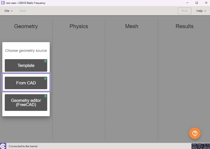
First we need to select the method with which we will load our geometry, in this case we will use the From CAD approach.
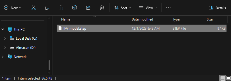
Click the blinking Folder icon to select the CAD files of your IFA antenna.

Select STEP files of your antenna and click Open to import them into CENOS.
note
For this example, we are importing only 1 STEP file (assembly). When working with your own CAD files, you can separate out the parts into multiple STEP files — perhaps one for the substrate and another for the conductive elements. It really doesn't make any difference in the simulation! Just ensure that each element has the correct position.
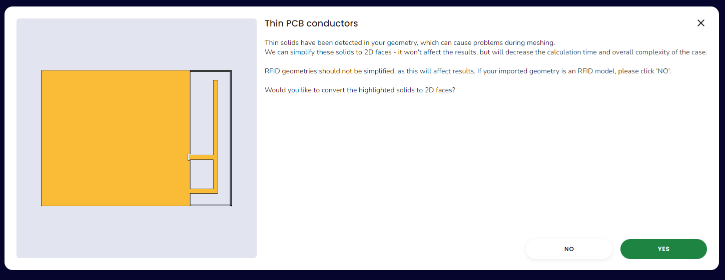
Thin PCB conductors
In case you are working with very thin conductors (<50um) these will be detected by the software and you will have the option to flatten them to work with 2D faces or you can continue without modifying the original geometry at all.
In this example our antenna and ground plane have a thickness of 35um and we will select YES to convert these solids to 2D faces.
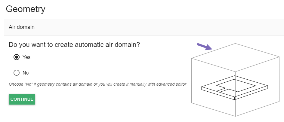
Generate air box
Once the CAD files are uploaded, CENOS will ask if you want to automatically generate the air box (ambient environment around your system). If your CAD model does not include the air box click Yes on the choice, and then CONTINUE.
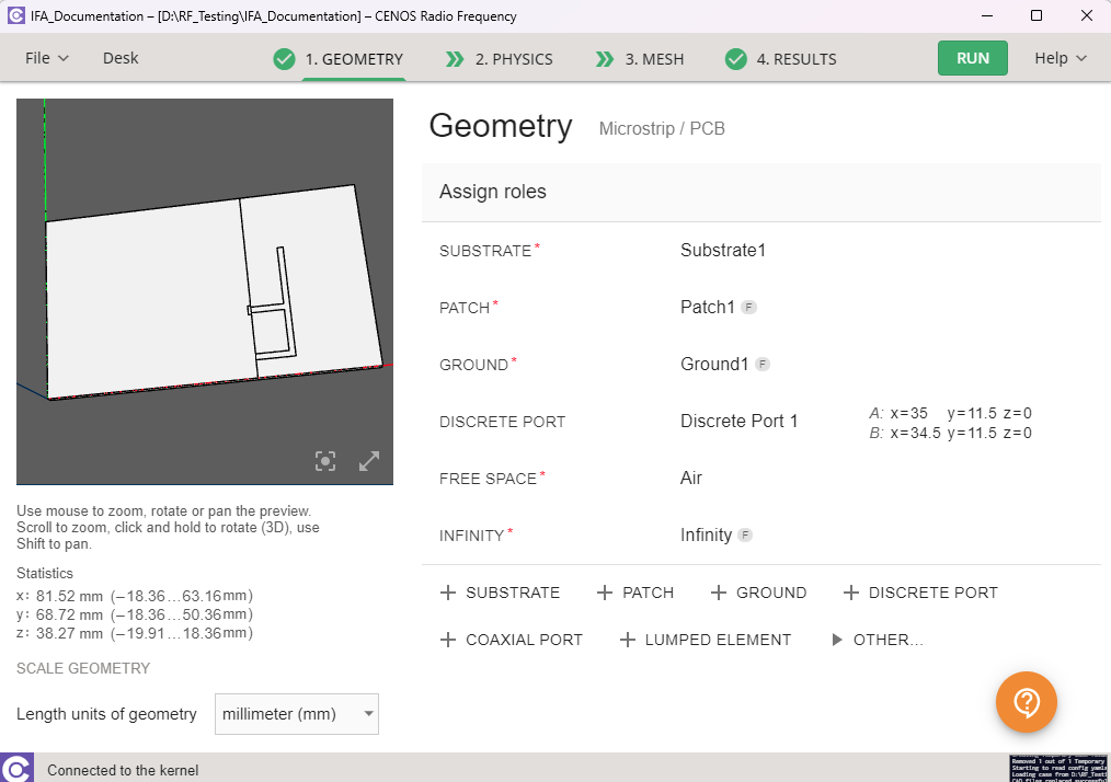
Roles
Before defining physics it will be necessary to define a type of application, as well as the roles of your system. Essentially you need to clarify which part of your geometry is the dielectric, which is the port etc., in other words, define roles for parts of your geometry.
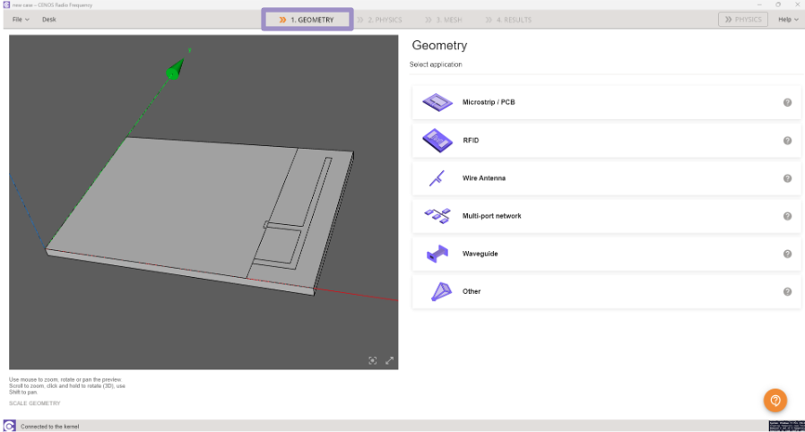
Type of application
This time we are working with a patch antenna, so we will select the Microstrip/PCB application. You will see that there are already some defined roles, which makes it easier to assign each element.
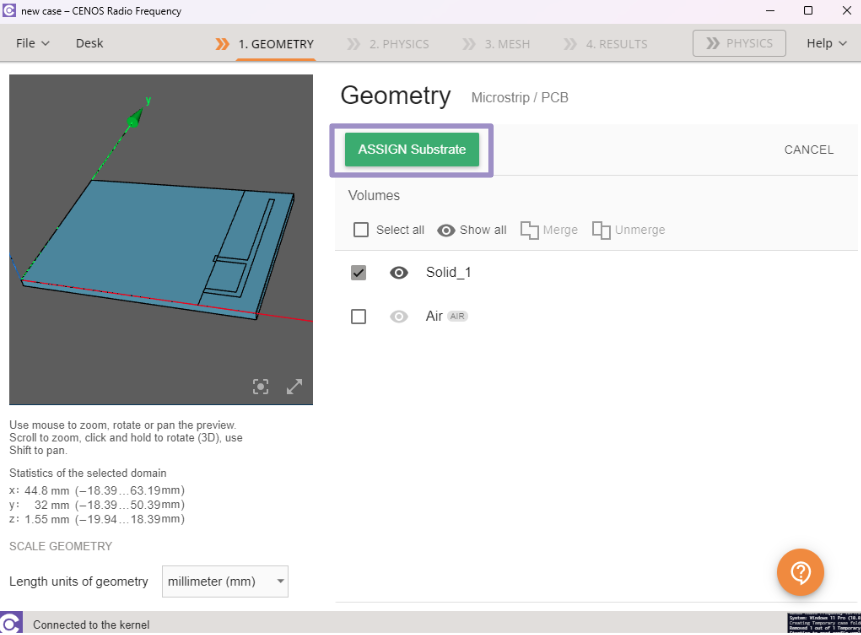
To assign the substrate role, simply click on it and choose the relevant solid from the geometry. The selected object will be highlighted in blue, and then click on ASSIGN Substrate.
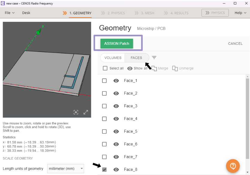
Continuing with the patch, since for this example we decided to flatten the thin conductors, it will be necessary to switch to the Faces tab when selecting this role. To continue with the process just click on ASSIGN Patch.
For the ground plane, the procedure will be the same as for the patch! Select the role and switch to the Faces tab. You will be able to choose the corresponding face and then click on ASSIGN Ground.
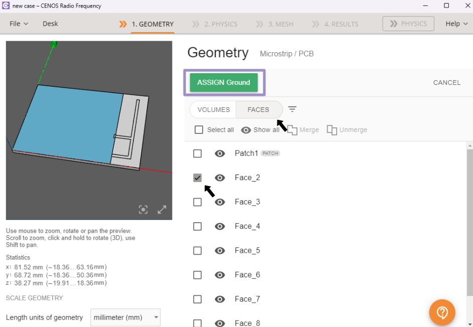
Finally we need to define the port. We will be using a discrete port so it is necessary to select two terminals, one on each conductive surface where you connect the feed in real life.
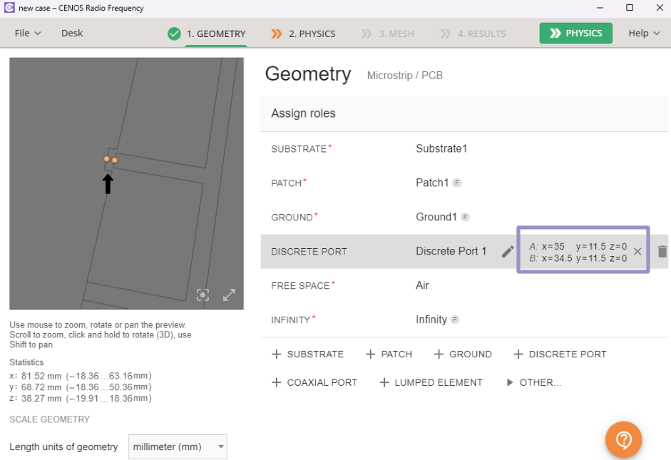
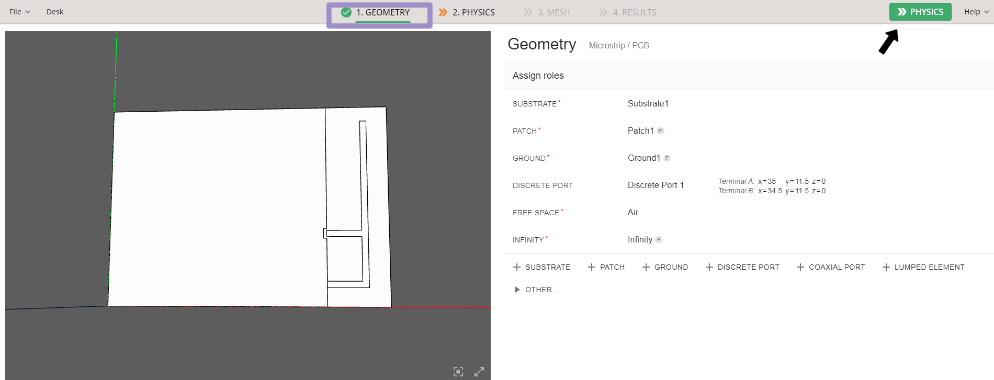
Go to Physics
Once all the necessary elements have been assigned, it is possible to move on to the Physics definition!
Physics
You will be redirected to the Physics window, where physical definitions are present. On the left you can see the preview window of your geometry, but on the right - the actual physical definitions. You can navigate physics through the domain tabs above the physical definitions.
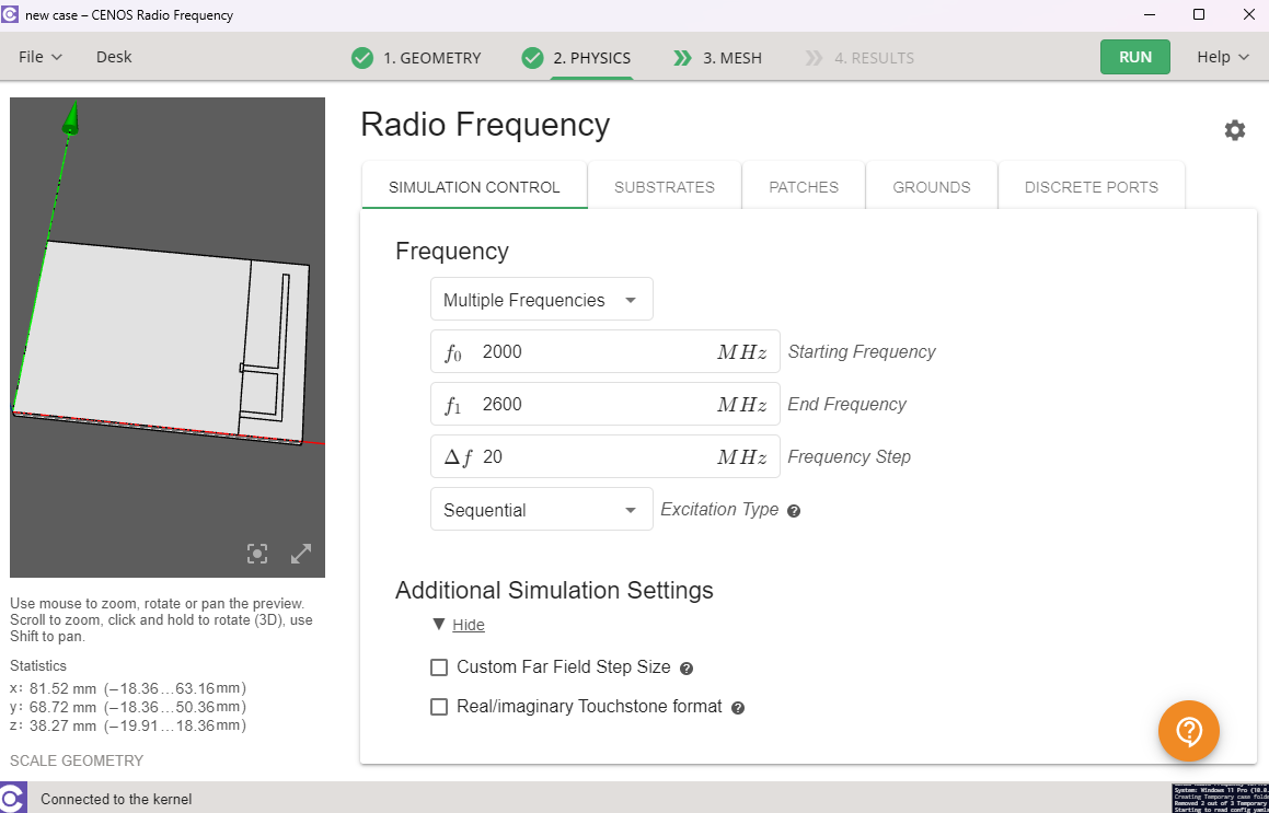
Simulation control
We will do a frequency sweep, for which we select the start frequency, end frequency and frequency steps in the SIMULATION CONTROL section.
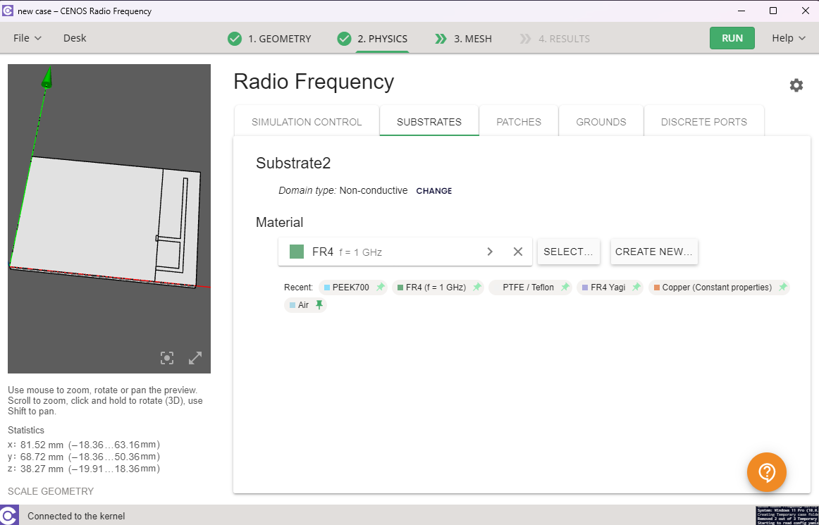
Substrate
Select the FR4 material that is predefined in the CENOS RF material library.
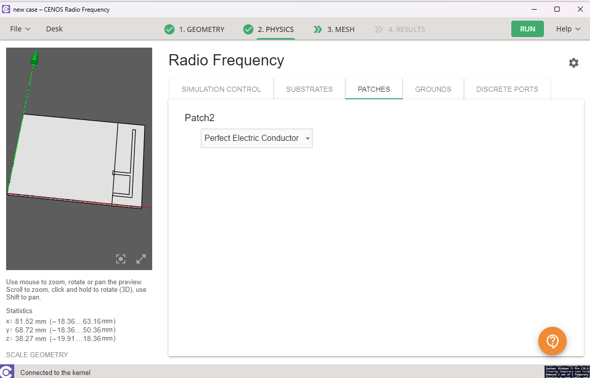
Patch
You will notice that the patch is automatically set to Perfect Electrical Conductor, for this simulation we will leave this setting.
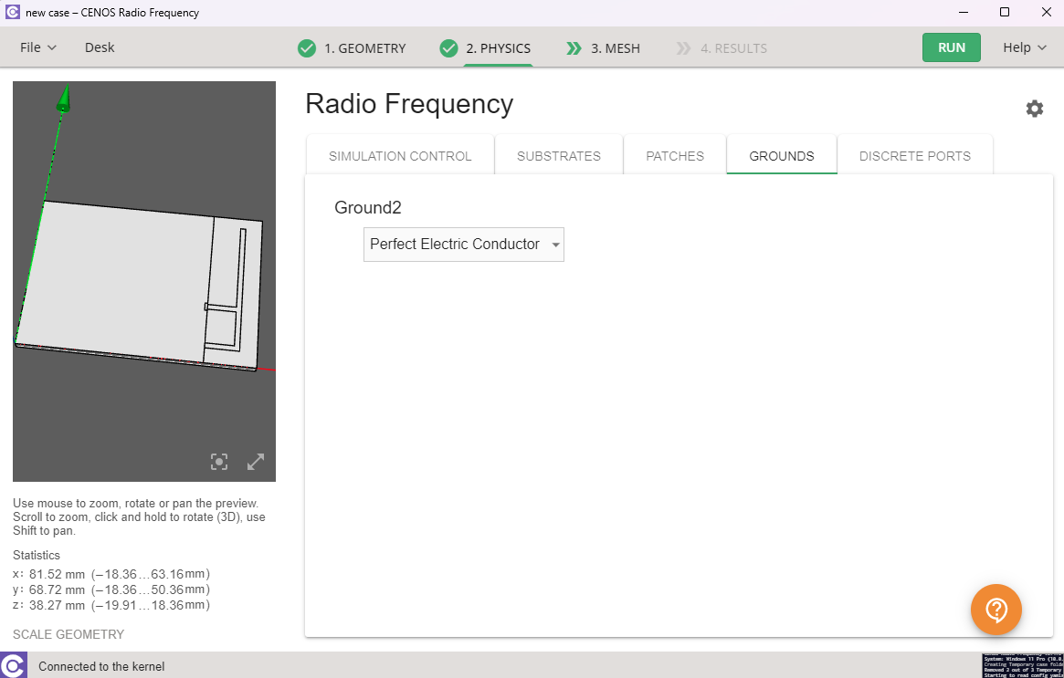
Ground
As with the patch, we will use PEC for the ground plane.
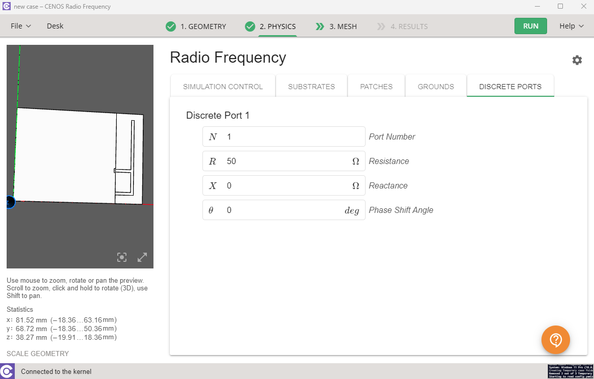
Port
Finally we have the port. For this particular case we will enter an input impedance of 50Ω.
Once all physical parameters are filled, it will be possible to move on to the meshing stage. You will notice that there are no more unfilled parameters once you see the Physics tab in green.
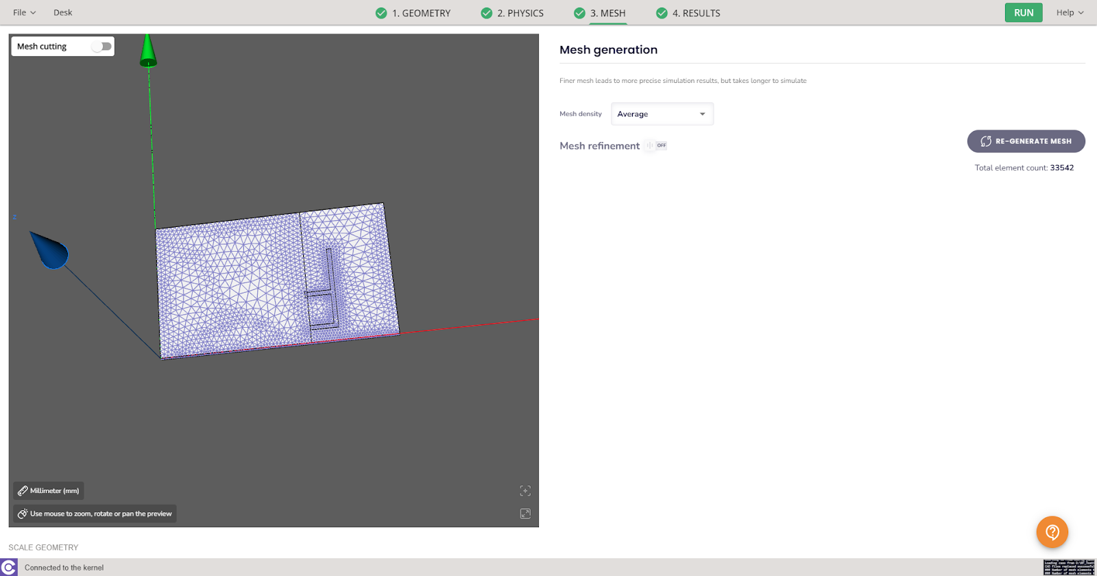
Mesh Generation
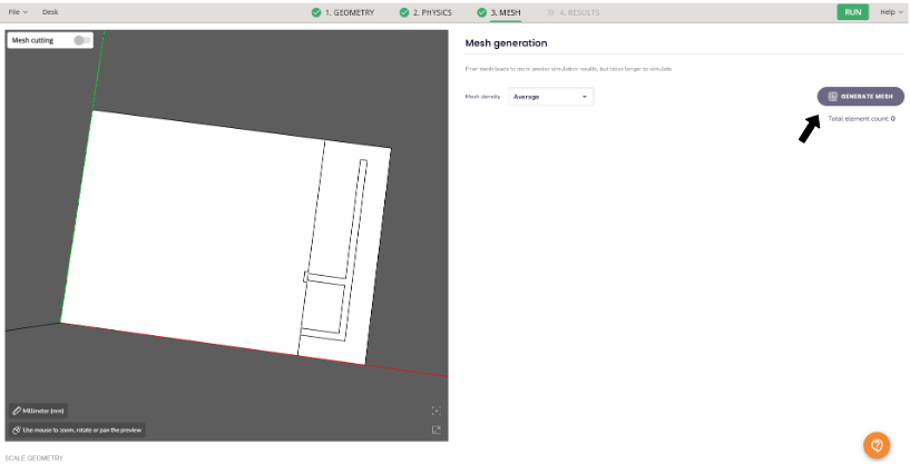
Once all physical parameters are filled, we need to create the mesh. CENOS gives you the possibility to create a mesh automatically, all we need to do is click on GENERATE MESH.
After a couple of seconds you will see on the left side a preview of the created mesh. You will notice that there are already some refinements applied, in case you want to modify further you can activate the manual refinements
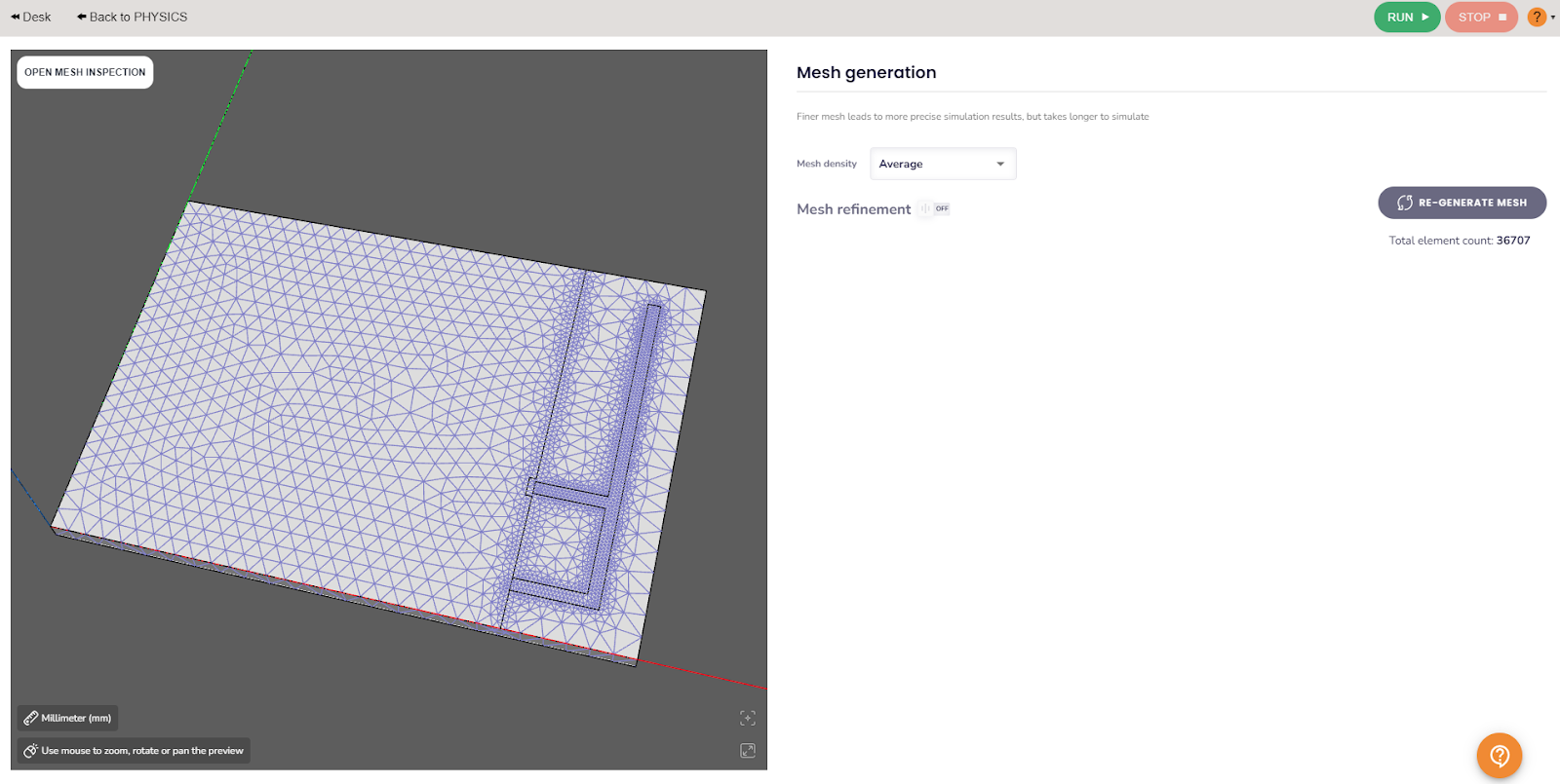
Finally click RUN to calculate your simulation!

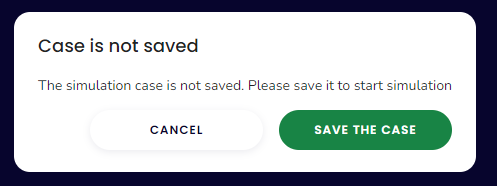
The software will ask you to save the case at this point, select the desired folder and once you save the case the simulation will start computing!
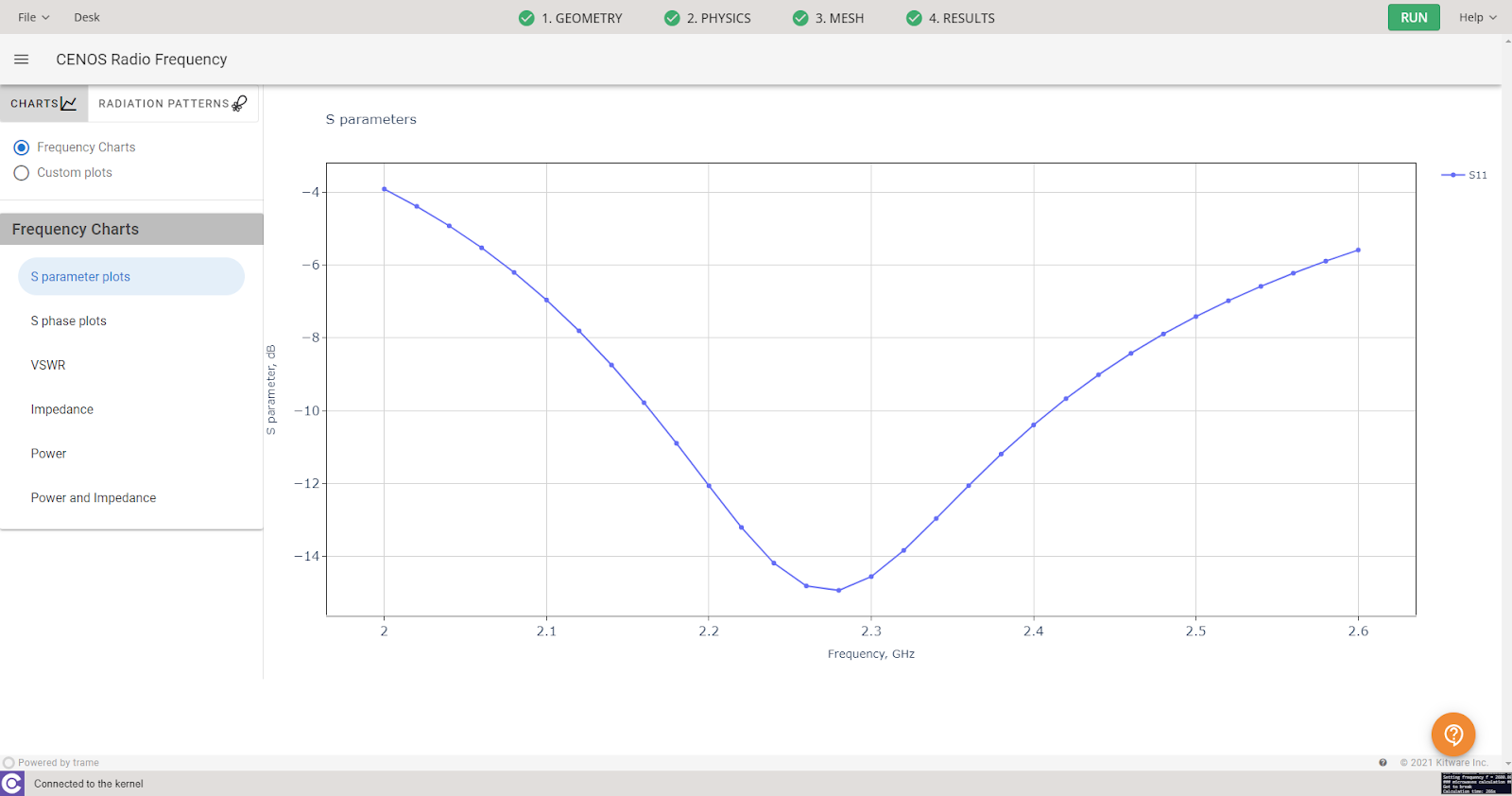
Results
When calculation is done, results will automatically open in a new window. Congratulations, you have successfully finished an Inverted-F Antenna simulation!
CAD replacement
If at a certain point you want to change the .step file because of a change in your geometry you can do so by simply going back to the Desk window and clicking on the folder icon under the From CAD box.

You can overwrite the results or save the file as a new case.

In the case that the new file only has dimension changes, i.e. no new solid or face is added, you will notice that both the roles and the physical parameters will be maintained. This allows you to save time since it will not be necessary to go through the steps we saw previously to set up the simulation.
Simply view the meshing section and regenerate the mesh so that the geometry changes are processed properly. Then just click RUN again and you will have the new results!