Folded dipole antenna simulation setup
In radio and telecommunications a dipole antenna is the simplest and most widely used class of antenna. There are multiple types of dipole antennas - the simplest ones you can simulate using CENOS Radio Frequency Templates, but for more complex ones (such as loop or folded dipole) Geometry Editor can be used!
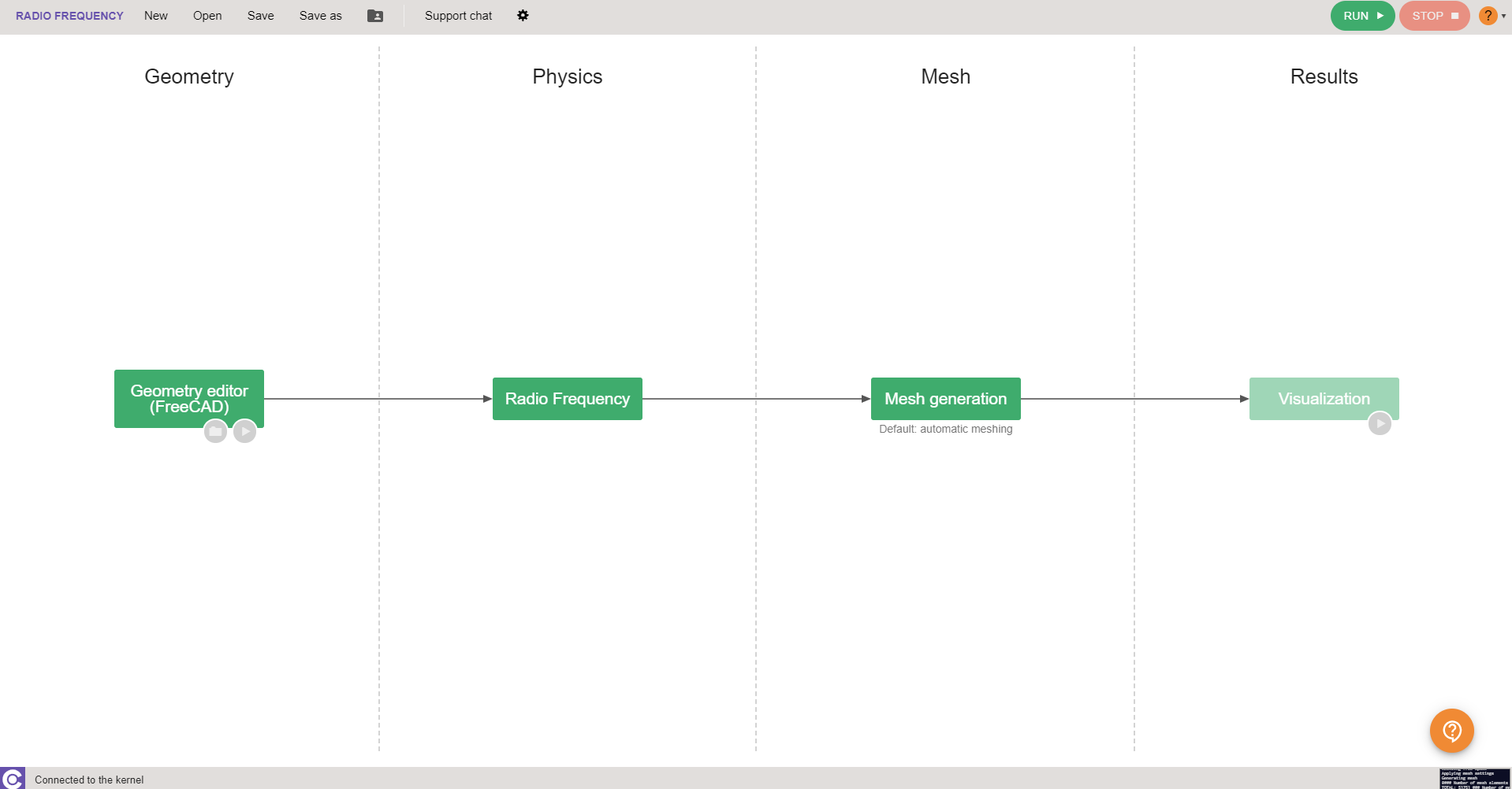
In this guide we will take a look at how to build a complete folded dipole antenna simulation from scratch in CENOS Radio Frequency app, using its built-in geometry editor, FreeCAD.
Case setup
Before we can actually start building our simulation, we need to first prepare our case - choose the way we will build our geometry, and save the case.
Choose geometry approach
You have three options from which to choose - Templates, Import CAD (if you have your own CAD file ready) and Geometry Editor.
For this example we will choose Geometry Editor and build our folded dipole geometry ourselves.
Save the case
At this point you need to save the case, otherwise if you try to open FreeCAD, CENOS will not let you move forward.

Once the case is saved, click the Play icon to open FreeCAD - CENOS geometry editor.

Geometry creation
In FreeCAD we have all the possibilities to build our antenna geometry, and we are going to do just that.
In this Geometry creation section we will cover all main points you need to complete to build your own patch antenna geometry manually.
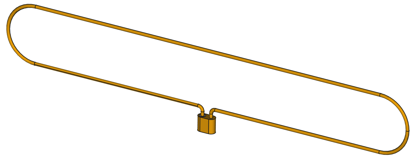
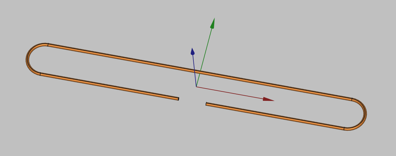
Dipole wire sketch
First thing we need to do is to draw the sketch of our wire. In Sketch workbench create a sketch and draw the wire outline.
note
For dipole antenna feed definition we can use a simple lumped port instead of a more complex SMA connector.
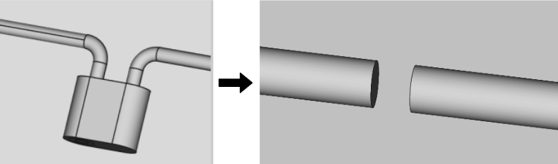
For this you will only have to leave a gap which is where the port terminals will be defined.
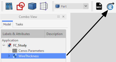
Wire thickness
Once the sketch is created, add wire thickness to the sketch to build the actual wire geometry.
With wire creation you have finished your geometry creation!
Send geometry to CENOS
Once you have finished the geometry, you need to send the mesh to CENOS. To do that:
Select all final objects in the tree view.
Click Geometry to CENOS.
As geometry is being sent to CENOS, FreeCAD study will be automatically saved in the simulation folder, so you can close it.
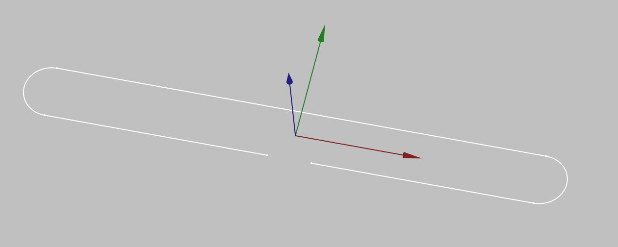
Roles
Once the geometry is finished and sent to CENOS, you need to define your geometry before defining the physics on it.
Essentially you need to clarify which part of your geometry is the antenna, which is the port etc., in other words, define roles for parts of your geometry.
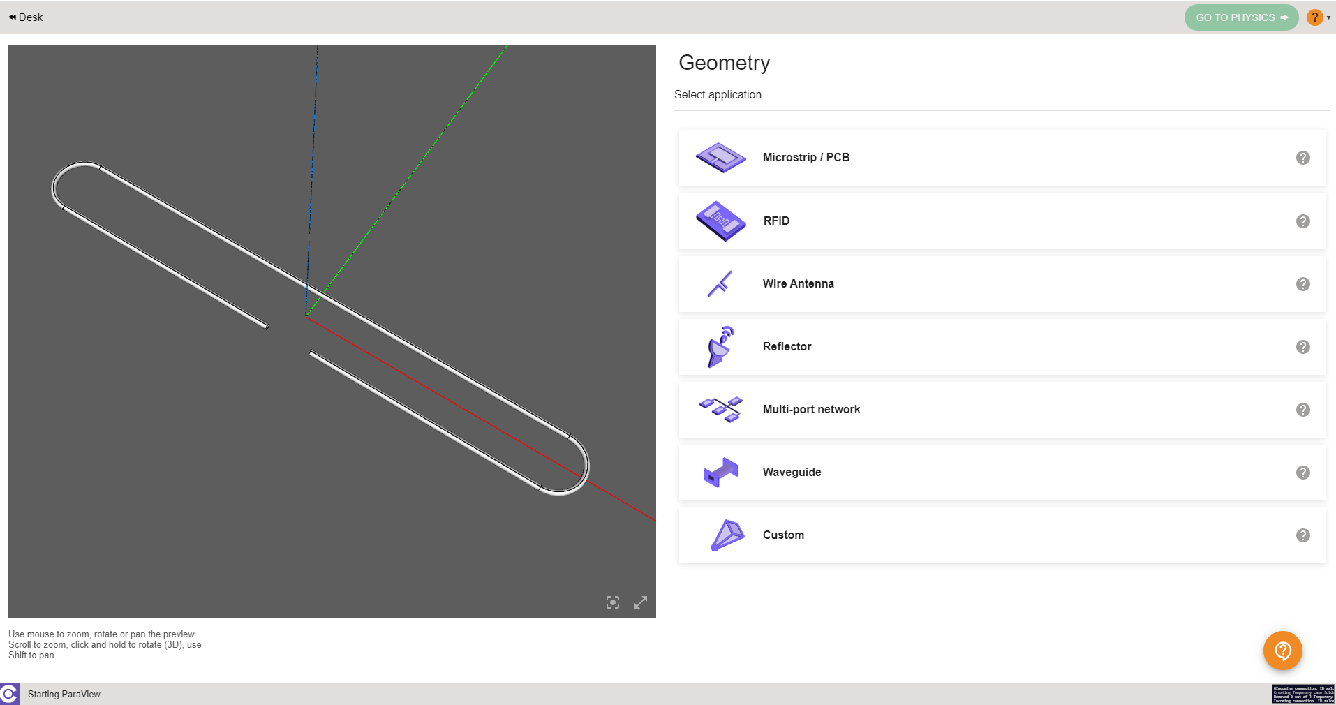
Type of antenna
Before you define roles, you need to select what kind of antenna you have - Microstrip, RFID, Wire, Reflector, Multi-port network. Waveguide or Custom.
For this example we choose Wire antenna type.
Roles
Now you need to define surface and volume roles for your wire and port.
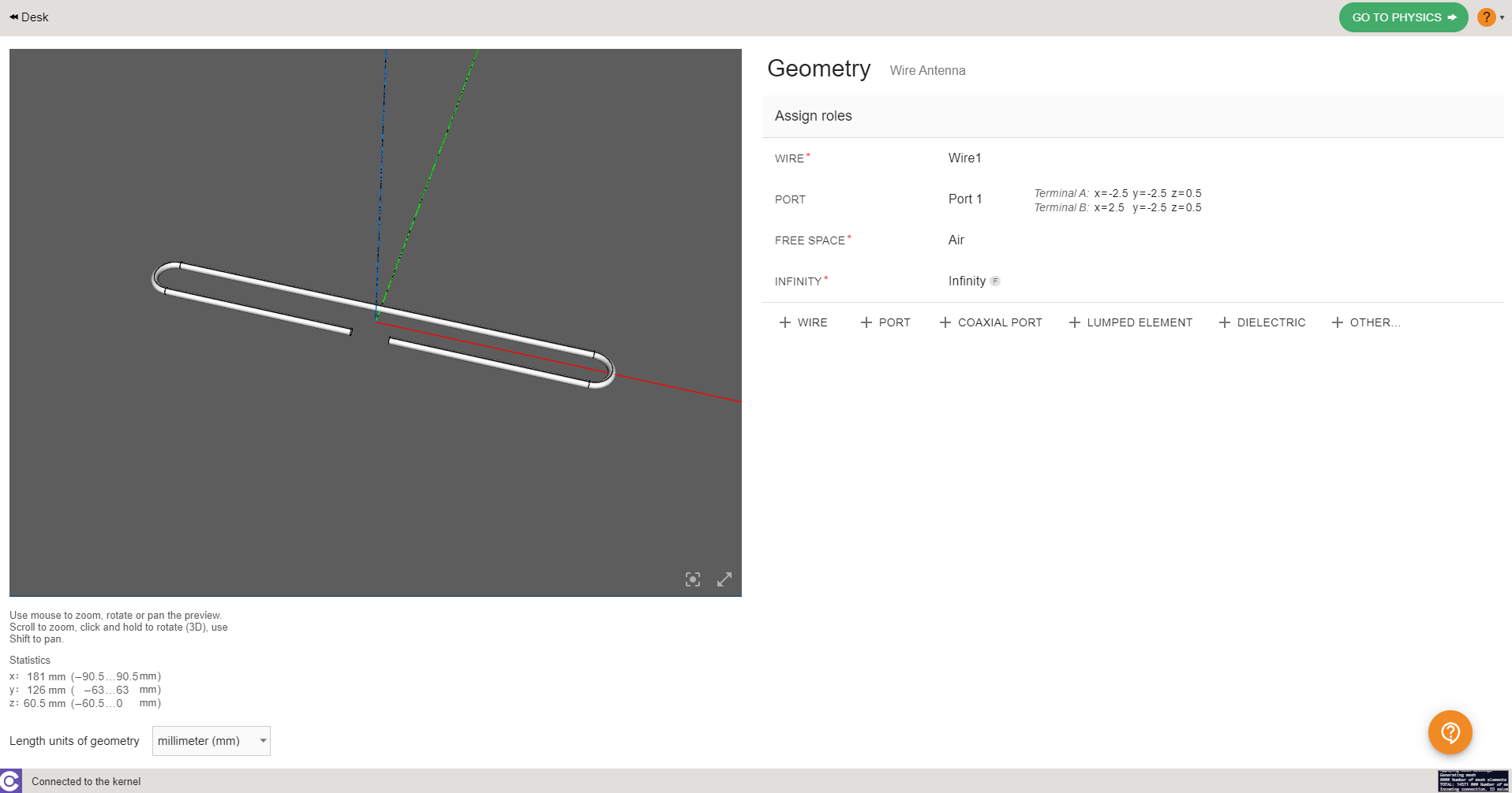
Got to physics
When roles are assigned, GO TO PHYSICS button will become active - click it to move to the Physics definition!

Physics
In physics you need to define the physical parameters of your simulation, which include frequencies, material definitions and boundary conditions.
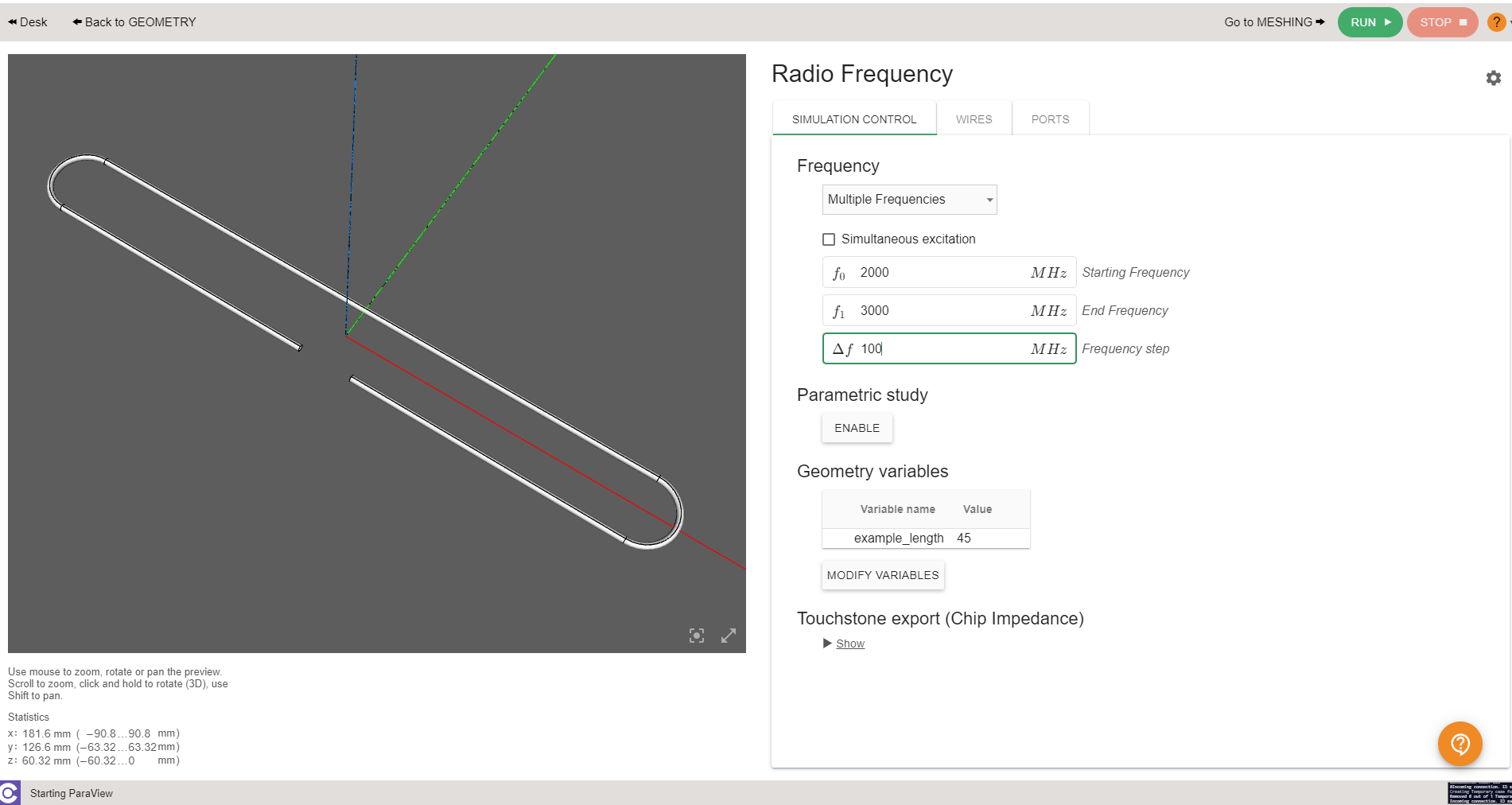
Simulation control
In SIMULATION CONTROL you define either a single frequency or a frequency sweep.
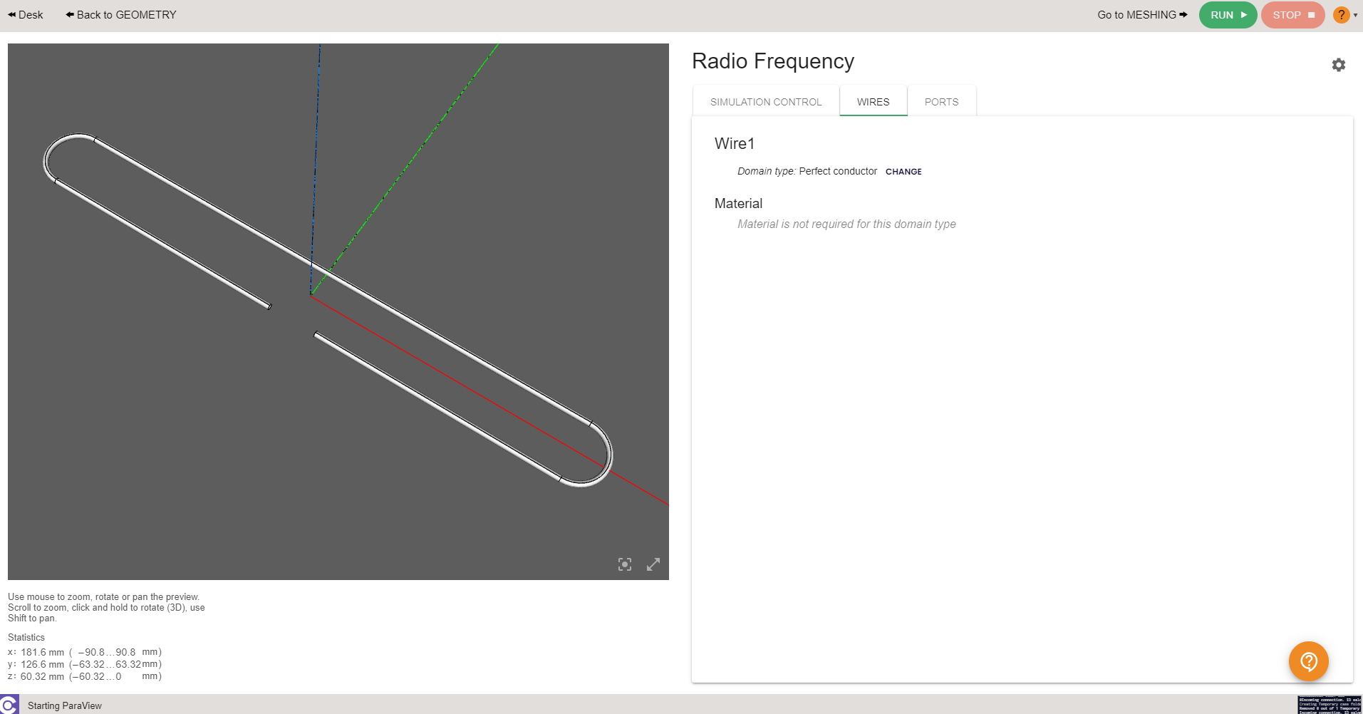
Wire
Wire is already predefined for you, so you don't need to worry about this part at all! Although, if you wish, you can change the antenna material.
Boundaries
Boundaries or boundary conditions have also been predefined:
Port → Default 50 Ohm Impedance.
Wire → Perfect Electric Conductor.
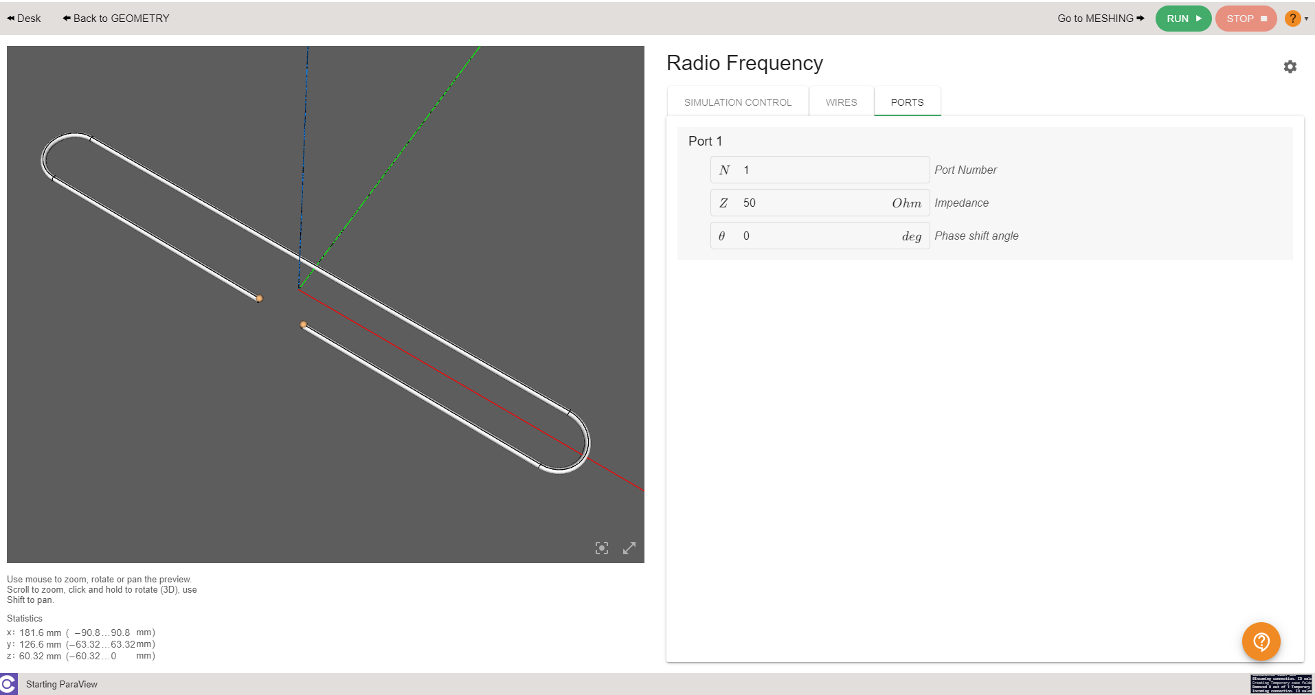
Once all physical parameters are filled, RUN button will become active and you will be able to run the simulation!

Manual meshing
If during the calculation you get a message about meshing problems, you will need to manually mesh your antenna. You can also mesh it manually already in the mesh generation section in case you want more control over your simulation.
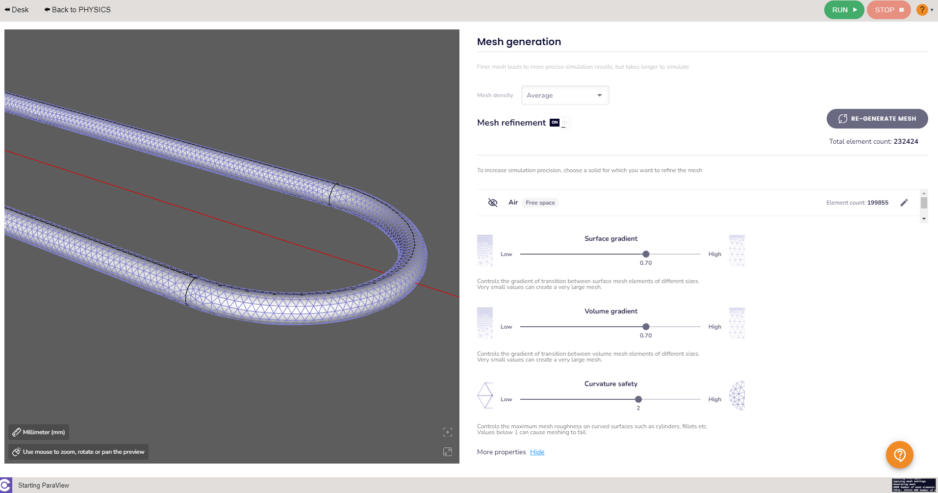
note
In wire antennas the curvature safety property plays an important role, decreasing this value will allow you to create a rougher mesh.
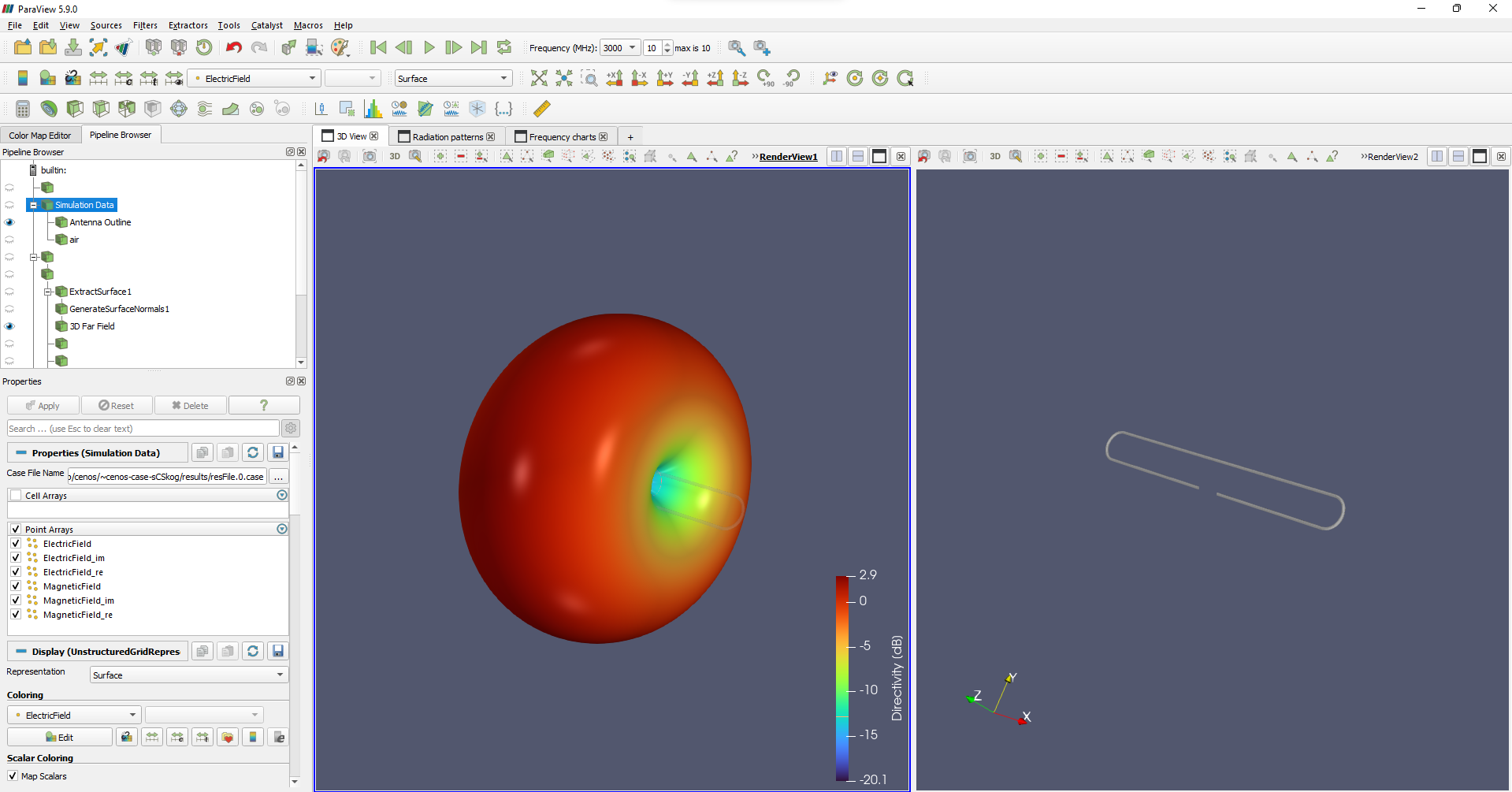
Results
When calculation is done, results will automatically open in a new window. Congratulations, you have successfully finished a patch antenna simulation!