Boundary conditions
Boundary conditions or Boundaries are very important part of the simulation, as they are needed to physically define your antenna design. Even though Boundaries are always filled automatically, in some occasions you will need to change or adjust the default definitions.
In this article we will go over the boundary conditions available in CENOS Radio Frequency app and learn the meaning of each definition.
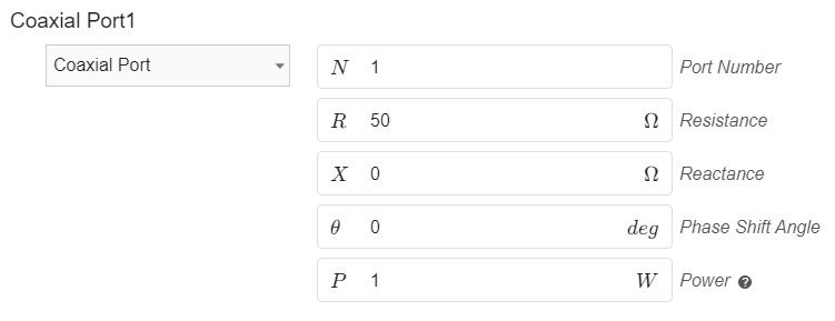
Coaxial port
This a boundary condition that will be automatically assigned to the face that has been defined with the Coaxial port role in the Geometry section. Port Impedance (Port resistance and reactance) by default is set to 50 Ohms, which you can easily adjust for your use case. Additionally, you have the option to specify a phase shift in the provided box for the port, allowing you to adjust the angle of wave excitation at the antenna input. Furthermore, you can enter the desired input power value to tailor the simulation parameters to your needs.
Perfect Electric Conductor
Perfect Electric Conductor is a condition which is by default applied to wire of wire antenna or conductive layers of patch antenna (patch and ground). It assumes perfect electric conductivity of the boundary.

Conductor
You can use Conductor boundary instead of Perfect Electric Conductor. Conductor takes into account the resistive losses, which can give more precise simulation results.

Radiation Boundary
Radiation Boundary is by default applied to the outer surface of the air box - a domain which is automatically generated around your antenna. By default, this boundary condition is hidden. The radiation boundary in CENOS uses the Silver-Muller absorbing condition.

Interface
Interface is used to define an internal contact surface between two separate domains.
