Manual meshing in FreeCAD
By default FreeCAD is necessary only for the geometry building, as the numerical mesh for your antenna is generated automatically when you calculate your simulation. However, in some cases the automatic meshing might fail, and in such occasion you will need to create your geometry manually.
If during the calculation you get a message about meshing problems, you will need to manually mesh your antenna in FreeCAD. You can also mesh it manually already when building your geometry (while still in FreeCAD) in case you want more control over your simulation.
General mesh
To create the mesh manually in FreeCAD:
- Switch to the Meshing workbench.

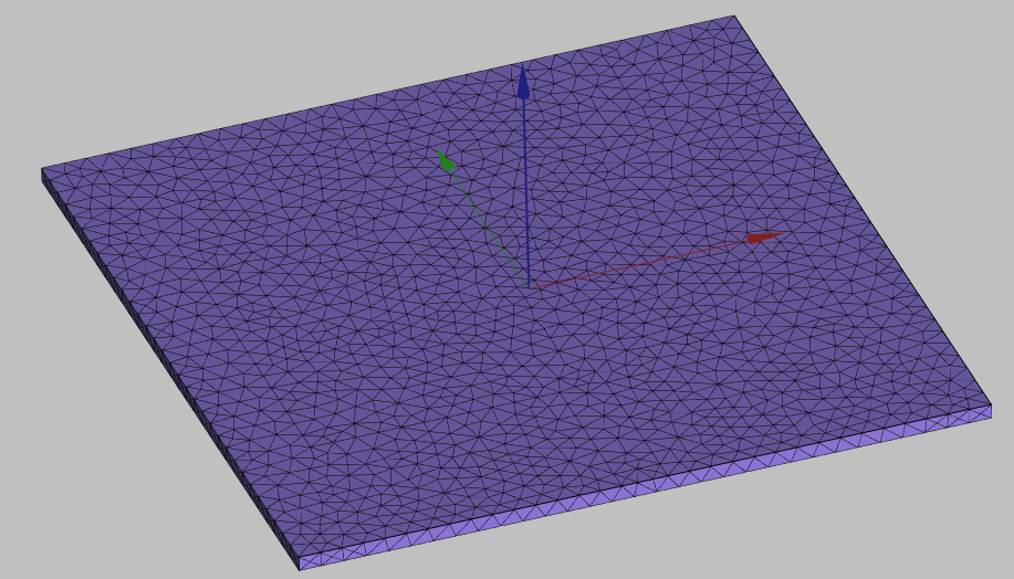
- Select all objects of your design from the tree view and click Create Mesh.

Mesh size will be automatically chosen and mesh generated.
tip
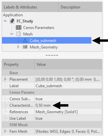
If you want to change mesh size, you need to click on the respective submesh and in properties change the Characteristics value.
General refinements
Based on the mesh we genereated previously, it looks like we meshed just a simple plate, but if we disable mesh visibility and visualize the original geometry, we can see that on this plate we actually have a patch drawing.
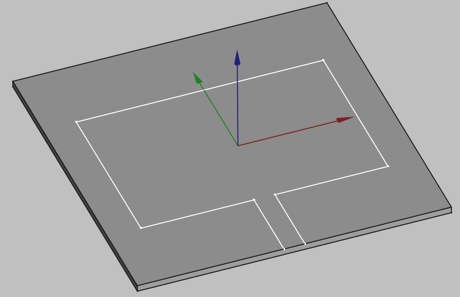
As you can see, the mesh we created for the box does not resolute the patch on it, so we need to create this resolution manually.
You can create a mesh refinement for elements (faces, edges, vertices) in the 3D view or whole objects (sketches, solids) in the tree view:
- Select the objects which you want to use mesh refinement.

- Click Refine mesh.

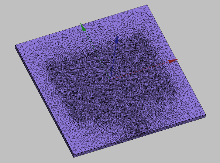
- Click Recompute mesh.

- Enable the mesh visibility to see the new mesh.
tip
To toggle visibility of any object, right-click on it and click Show/Hide selection.
Patch meshing
Different antenna types might require different meshing approaches to optimize the simulation. In this section we will take a look at different meshing approaches specific to patch antennas.
Outer edge refinement
For patch antennas we often need to refine the mesh of the patch, but we don't need to refine the whole patch, because the Electric and Magnetic field gradients are the strongest on the outer border of the patch.
For such cases we need to refine the outer edge of our patch, which will create a good resolution of the outer border of the patch, but will still leave quite coarse mesh in the middle of it, which will bring down the mesh element count and optimize the calculation, while increasing the precision of our results!
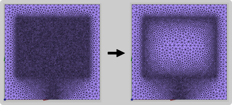
To create such edge refinement:
- Create an additional edge in your sketch (in the middle of the patch). This will work as a reference edge for keeping the mesh element size in the middle of the patch large.

- Before creating mesh refinement, enable the visibility of the sketch and select the outer edges of your patch. Leave the internal edge unselected!

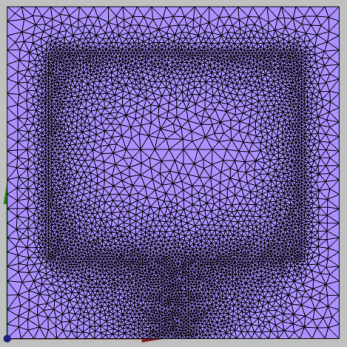
Now just create the mesh refinement for the selected edges, and you have created an optimized mesh for your patch!
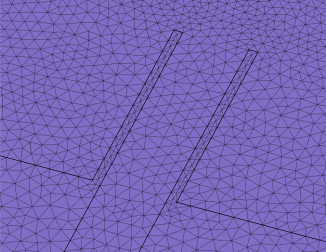
Inset refinement
For patch antennas with insets it is important to resolute the inset gaps through mesh sufficiently, as incorrect mesh in these parts can affect the results.
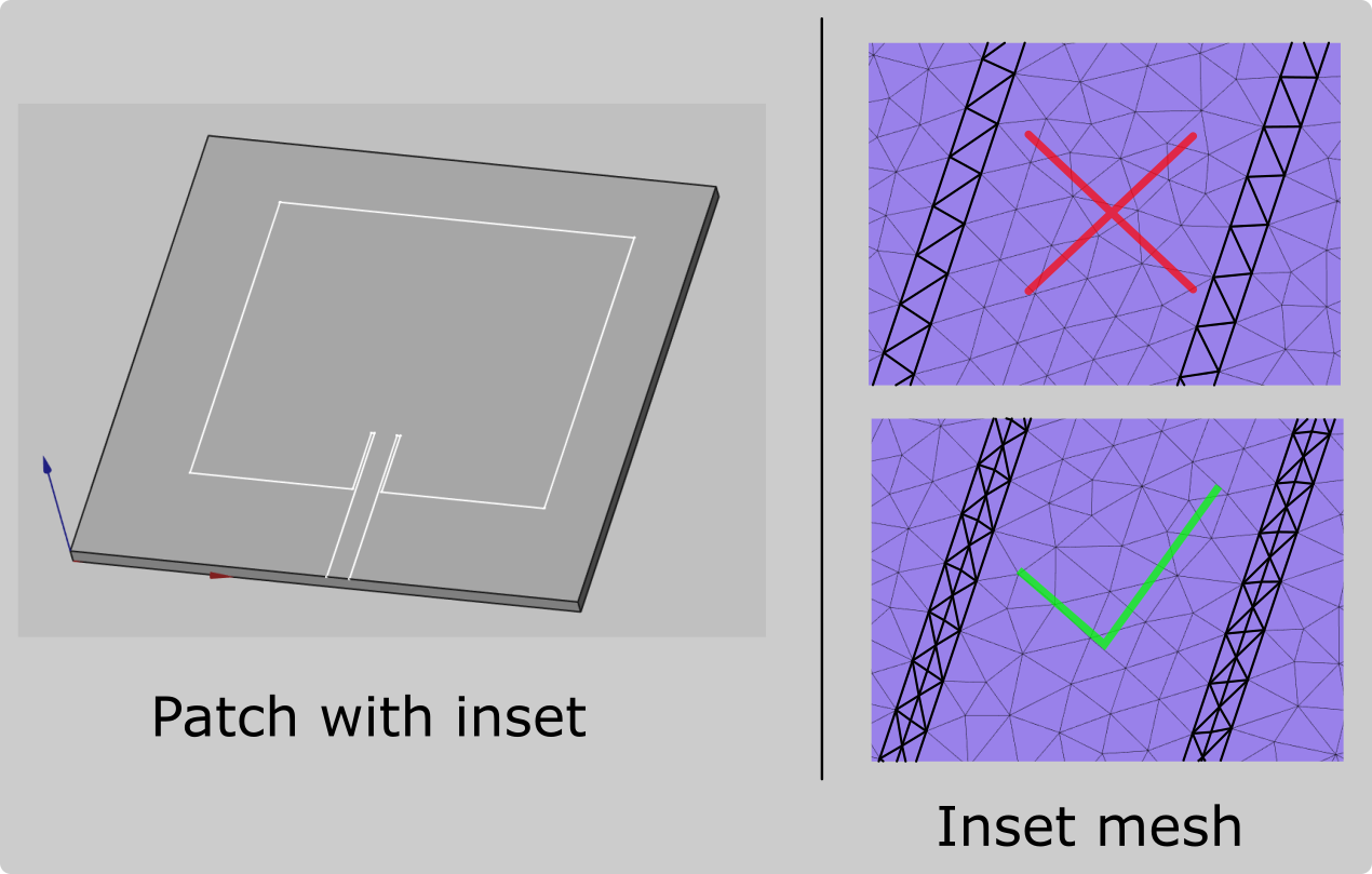
To refine mesh in these places:
- Create two additional edges in your sketch (in the middle of both insets). These will work as a reference edges for decreasing the mesh element size in the middle of the inset.

- Before creating mesh refinement, enable the visibility of the sketch and select the two edges in your inset parts.
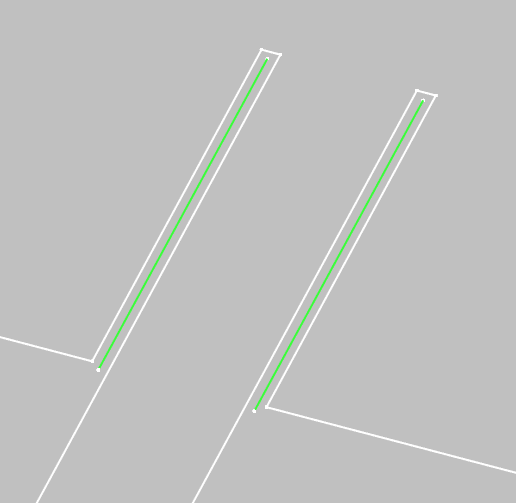
Now just create the Mesh refinement for the selected edges, and you have refined your inset parts!
Meshing errors
Meshing can sometimes be frustrating, as you try to build the mesh, get an error, but cannot understand what is the actual problem and how to correct it.
In this section we will take a look at some of the most commonly seen errors during meshing, and how to fix them.
note
When the mesh is calculated but an error is present, you need to pay attention to the error messages. Depending on the errors there are different ways to correct them.
Ill-shaped tets
Error message Warning: X ill-shaped tets are still in the mesh seems to be the most common one. It usually causes problems when sending the mesh to CENOS.
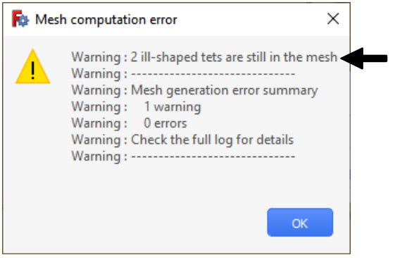
SOLUTION
Change the submesh element size slightly. This error can be very sensitive to the element size, try making them smaller or larger.
Invalid elements in surface
Error message Warning: X elements remain invalid on surface XX indicates that the generated mesh has some problematic elements that needs to be corrected.
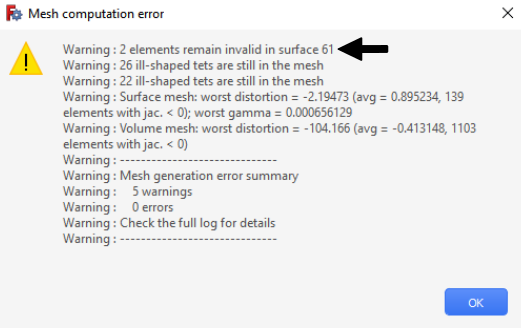
If this happens, the surface (on which the invalid elements are reported) will be visible in the Mesh Error elements group in the tree view.
To visualize the problematic surfaces, disable the sub-mesh visibility (they will appear red).
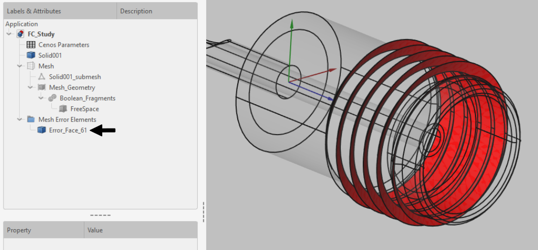
SOLUTION
Simplify the problematic surfaces (remove the thread in the example).
Volume mesh: worst distortion
Error message Warning: Volume mesh: worst distortion is actually not an error, but a warning, which indicates that there are some elements which are quite distorted and might impact the simulation results.

In case of such warning you can still use the mesh and send it to CENOS, but be aware that it could impact the result accuracy!
SOLUTION
Decrease the submesh size, it should create smaller mesh elements and correct the element distortion.
Send mesh to CENOS
Once you are satisfied with the mesh, click Send mesh to CENOS!