Geometry creation in FreeCAD
For geometry manipulations CENOS Radio Frequency uses a very strong geometry editor - FreeCAD. This editor is used in the Geometry Editor workflow, so it is important for us to understand how to work with FreeCAD.
Watch a short video on how to use FreeCAD for CENOS Radio Frequency app:
Geometry import
Sometimes when building an RF simulation, you will already have pre-made geometry, which you can import into FreeCAD for additional geometry manipulations.
DXF/STEP/IGES
You can easily import your CAD file in DXF, IGES or STEP file formats.
To import such files, open Geometry Editor and simply drag & drop your geometry into FreeCAD!
KiCAD PCB files
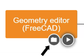
To import KiCAD PCB files directly into CENOS RF, select the Geometry Editor approach and there you will need to click on the folder icon to load your geometry.
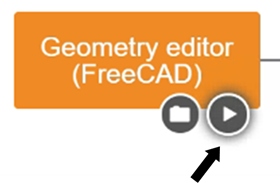
Once you have selected your file you will return to the main CENOS interface where you will now click on the play icon. Then the software will ask you to save the case and, after this, FreeCAD will automatically open with your geometry!
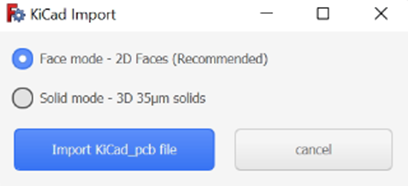
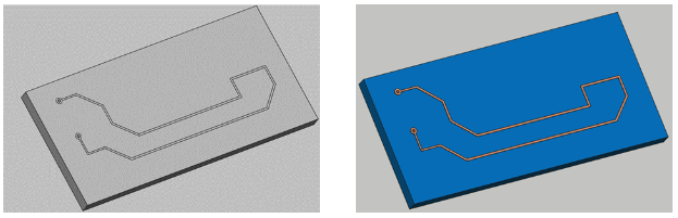
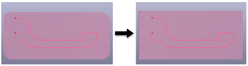
You have the option to use your model completely in 3D or flatten the thin conductive parts, such as tracks, to have them in 2D. We recommend selecting the Faces mode, as the results will not be significantly affected but the mesh will be easier to create and the calculation time will be reduced!
important
RFID geometries should not be simplified as 2D faces as this will affect results.
note
We recommend that for the substrate you use a geometric figure without curvatures since this would cause troubles reading the geometry and it will not be imported correctly into FreecCAD. If the curvatures in the substrate are important in your model, you can create it within FreeCAD once the model has already been imported.
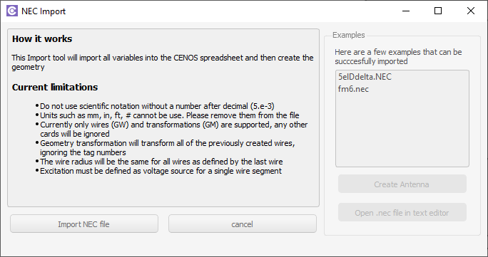
.NEC
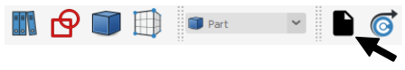
If you have a .NEC (or other format) file, you can import it from the Part module.
Unit scaling
CAD files which are imported in FreeCAD must be in the correct units - milimeters. If your geometry is scaled incorrectly, you need to rescale it, otherwise meshing problems will occur.
To scale your geometry:
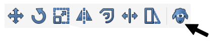
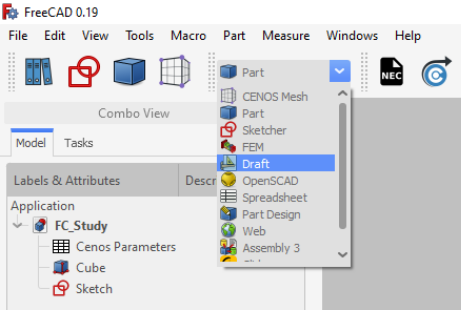
- Switch to Draft workbench.

- In Tree View select your geometry and click Clone (this function will create a scalable copy of your geometry).
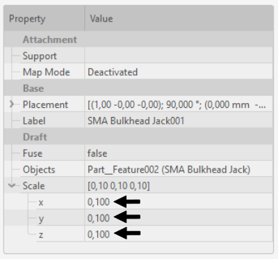
- Once the clone object is created, scale your geometry in Properties. Make sure that the scale factor is the same in every direction to avoid distorting your geometry!
note
As an alternative to geometry scaling you can use Scale function, but it will not work on every geometry, as opposed to the Clone approach.
CAD compound check
If you have imported one or more CAD files and stumble into a problem either at meshing or anywhere else, it might be an indicator that the CAD file is actually not a solid, but a compound of surfaces, which can cause problems for FreeCAD.
To check if your CAD is a solid:
Click on the object in Tree View and open Python console (right-click on the icon toolbar and select Python console)
On the lower right corner Python console will open. Write len(obj.Shape.Solids) and click enter.
Take a look at the output.

The number of solids indicate how many volumes are there. If this number is high, evaluate the quality of your CAD file!
note
If you get an error message and cannot display the number of solids, click Edit → Send to python console, and redo the previous steps!
Component Library
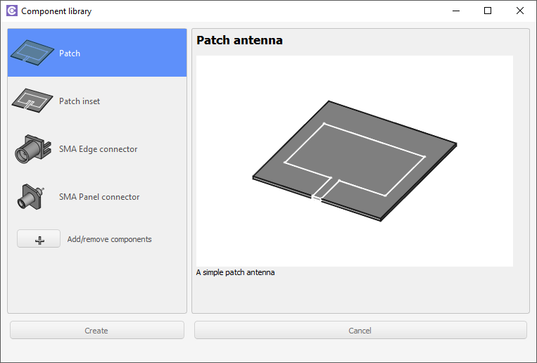
You can use CENOS Component Library templates to build or add patch or SMA connector geometries.

Patch antenna
Select the patch you want to build and click Create.
You can change the parameters for the template by clicking on the spreadsheet titled "Patch Parameters" or "Patch inset parameters" if you chose the patch with an inset.
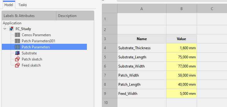
tip
To navigate between Cenos Parameters and geometry preview, use the tabs below the spreadsheet.

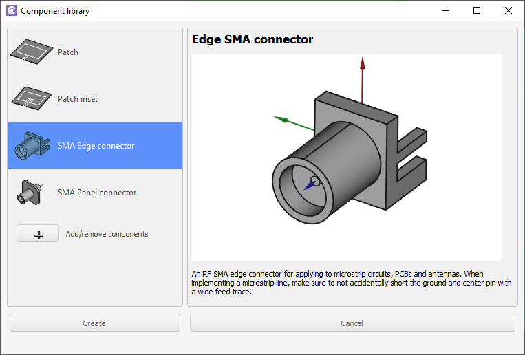
Coaxial edge connector
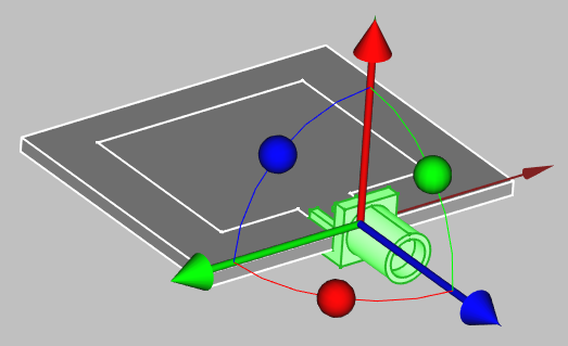
Select Coaxial edge connector and click Create.
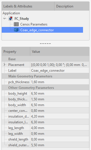
The connector will be automatically placed in your workbench, so you can position it by right-clicking on it in the tree view and selecting Transform.
To change the size of the connector, select it in tree view and edit the Property tab to suit your application.
Sketches
A sketch is the base for almost all geometrical objects you can create, including geometries for RF models, which is why we need to know how to create one.
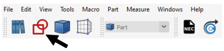
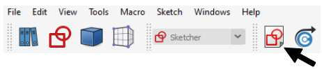
From scratch
In FreeCAD you can create sketches in the Sketcher workbench, which you can access directly through the shortcut icon:
Once in the workbench, click Create a new sketch.
Select the plane where you want to create you sketch, and you can start to draw the actual geometry.

FreeCAD offers a large variety of tools designed to easily and precisely create any geometry.


tip
Hold down Alt to rotate the camera in sketch view
Draw your model's geometry, and, once you are done, click Close.

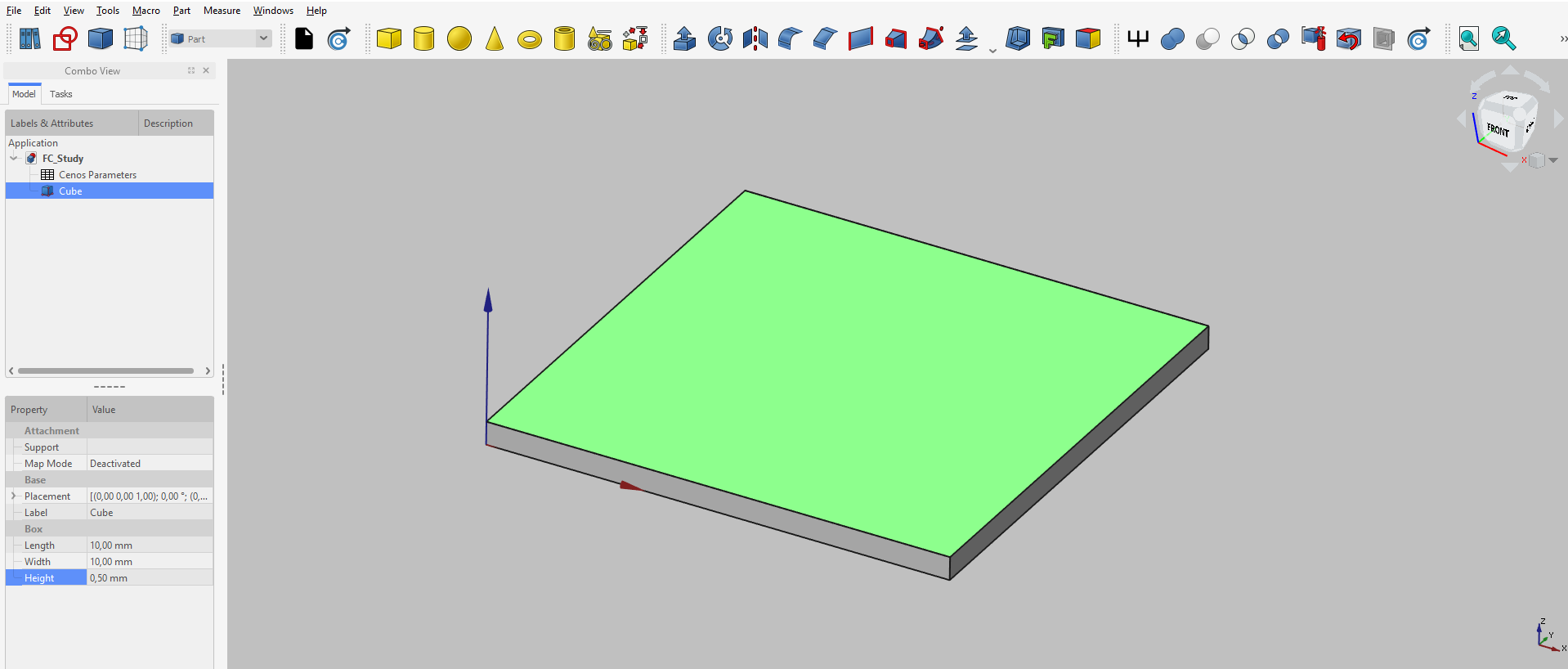
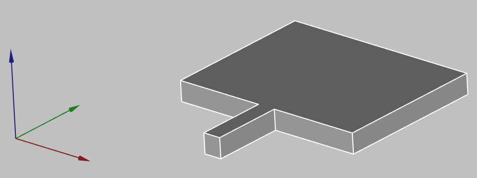
On volumes
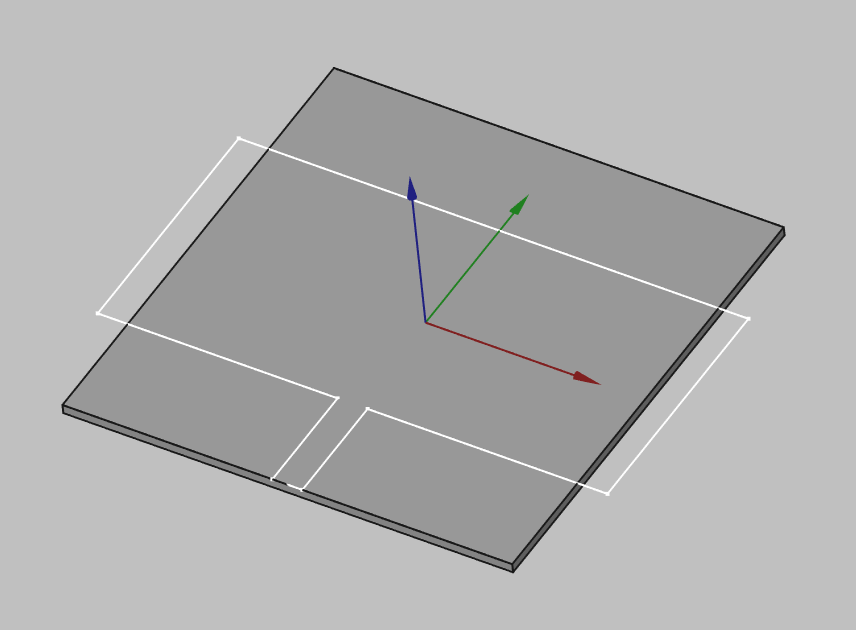
In some cases it is beneficial to create a sketch on an already created volume, for example, PCB antennas. Once you have created a 3D volume, for example, a box, you can select one surface on which to create your sketch.
note
The geometry you create will be partitioned upon sending it to CENOS, which means that sketches created on top of volumes will appear as separate surfaces in CENOS!
For example, you don't need to create an extrusion for patch, as it is enough to create only a sketch for it.
In the Part workbench select the face on which you want to draw.
Click Sketcher workbench.
Then click Create a new sketch.
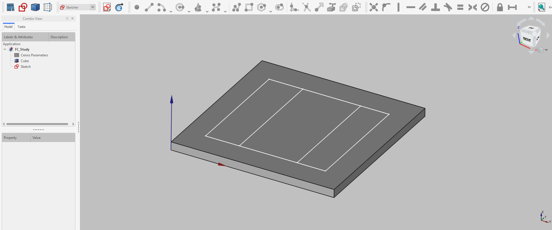
Click OK to FlatFace definition, and start to draw.

tip
Hold down Alt to rotate the camera in sketch view
Once you have finished drawing your sketch, simply Close it and you are done!
3D volumes
For a lot of times it will be necessary to create 3D geometries, not only 2D sketches. Fortunately 3D modeling in FreeCAD is very straightforward!
important
When creating volumes, make sure that they do not overlap with each other. Overlapping volume objects are forbidden!
Basic Shapes
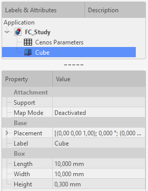
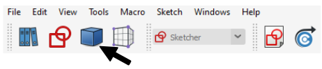
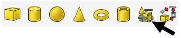
For the simplest volume objects like cubes, spheres or cylinders, FreeCAD offers an easy way of creating such geometries. As you open FreeCAD, you will be automatically put in Part workbench. There you can simply select any geometry you want and build it.

As you select an object, it will be built with a pre-defined size. To change the size of your geometry, select your object and change its properties.
Extrusion
For more complicated geometries it is possible to draw a sketch and create a 3D volume object from that sketch. There are multiple functions for this procedure, but the most commonly used one is Extrusion.
To use Extrusion, you need to first create a sketch you need.
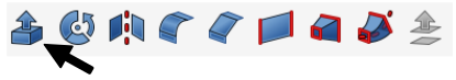
Then switch to Part workbench
and click Extrude a selected sketch.
In Extrude properties window define the extrusion lenght, check Create solid and select Sketch as a shape to extrude. Once done, click apply.
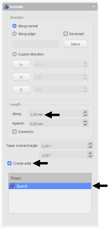
Now you have succesfully created a complex 3D object!
Wire thickness
To create a wire antenna from scratch, you need to create a sketch of your antenna, and then define the thickness of your wire:
CREATE A SKETCH
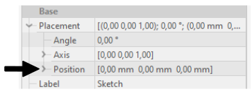
- For 2D sketches you can set sketch position in its properties (In sketch properties Base → Placement → Position)
- To build 3D sketches, use Draft Workbench → Drafting → Line. There you will need to build lines one by one and adjust the Start and End points to match your design.
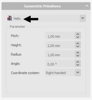
- For helixes or spirals use Create Primitives function in Part workbench.
In Geometric Primitives properties select Helix shape, and define your wire.
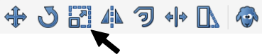
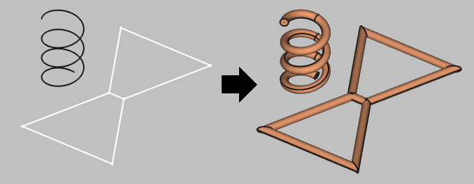
Create a wire with volume from the edges, select your shape, click Wire thickness tool in Part Workbench and define the wire thickness.

caution
Sometimes when building wires, the visualization will appear like this:
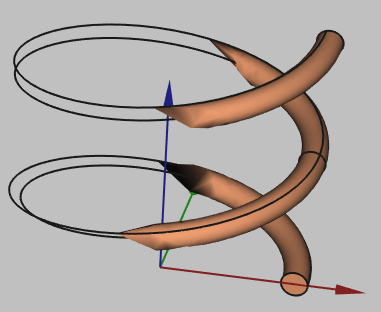
This is a visualization problem, which does not affect the geometry itself. You can continue and use this geometry in your setup!
Geometry parameters and Parametric study
A very useful thing to have is parameterized geometry. This way you can create your geometry and dynamically change it through parameters without the need to rebuild everything, as well as perform a parametric study of your geometry.
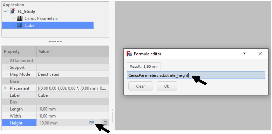
You can define parameters in the Cenos Parameters spreadsheet where you can use various units and/or mathematical equations for the values.
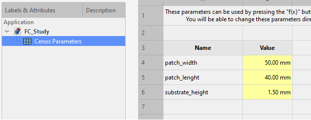
To use these parameters, click the Formula Editor button in the value field and then enter CenosParameters.name.
caution
Make sure to constrain your model's sketches and check all the values you want to simulate if you intend on performing a parametric study! Otherwise, your sketches might hang over your base geometry and the simulation will fail!
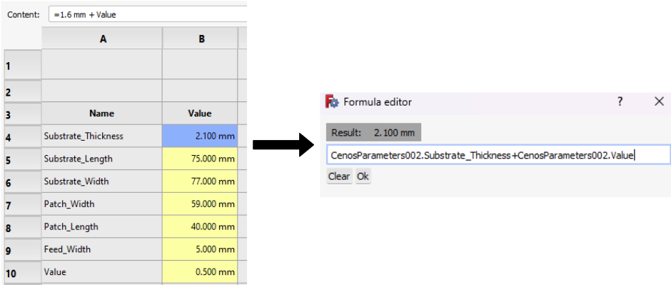
important
If you would like to create a variable whose dimension is based on another variable, you need to do this definition in the Formula Editor. If you do it directly in the spreadsheet, updating the data will not take effect on the results of the parametric study.
Once you have finished working on your model and assigned all the parameters you are interested in, you can send the geometry to CENOS, where in the Physics section you will be able to start the parametric study.
Getting the geometry to CENOS
To send your finished geometry to CENOS, you have to:
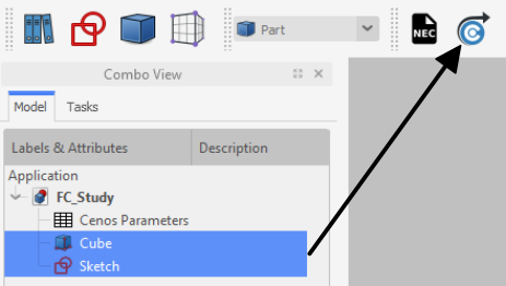
Select all final objects in the tree view.
Click Send Geometry to CENOS.
As geometry is being sent to CENOS, the FreeCAD study will be automatically saved in the simulation folder, so you can close it.